


Help
How can we help?
Learning how to create Revit families can be an essential skill to have in today's job market.
Building Revit families from scratch is not something that's easy to learn on your own, however. That's why we've compiled a free collection of Revit tutorials that will help you learn how to create Revit families yourself. Visit the BIMsmith Free Guide to Revit Family Creation to learn more.
How to Create a Revit Family Step By Step
Here's a step by step breakdown of what's covered in the above Revit tutorial video.
 Revit Family Creation 101 - Intro to Creating Revit Families - YouTube.png)
-
-
1. Start with the basics.
Before you start drawing, think about how you want the family to act and how you want the user to interact with the final family.
A. Choose a Template
There are a lot of template options, but most of the time, “Generic Model Face Base” should be a good template to use.
B. Create a Skeleton
It’s best to start by drawing left and right reference planes, use the aligned dimension tool to snap to the center origin point, then do the same for front and back (don’t forget to make them equidistant). If you want to snap to them when loaded into a project, give the reference planes specific names such as “width” or “depth”.
Beginning Tip: Constantly check on your project. Flex the model to make sure it is functioning how you want it to.
Beginning Tip: Always name your parameters. This will help in the long run to know what you are editing.
 Revit Family Creation 101 - Intro to Creating Revit Families - YouTube.png)
-
-
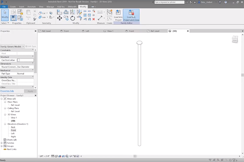
2. Start drawing.
A. Create the Base
Draw the base for the parent family by using the extrusion tool. In order to lock the sketch lines to the reference plane so you are able to flex the model, choose the lock button and select the desired reference planes to trim it back into place.
B. Edit in a Different View
Go into an elevation view. Create a reference plane for height and another one for thickness values. Make sure to assign parameters to the different planes. Don’t forget to test and lock the geometry.
3. Create the other families that will go into the parent.
A. Create a New Skeleton
For this, you will have to create a new family, but this time you can use the generic model template, it doesn’t need to be face based.
B. Draw the Shape
Draw a simple extrusion and lock to the reference planes. Select and apply a radius label to control the radius once loaded into the parent family. Then, select that label and make a new parameter for it.
C. Add Reference Planes
Do the same thing that you did in the parent family: create a reference plane height and lock extrusion to the top and the bottom. Make sure to lock the top and the bottom, then test it out and make the family reflect the height of the table legs.
D. Add a Diameter Parameter
Since most people don't think in radius, we are going to add a diameter parameter that will eventually be controlled in the parent family. Add a new formula (Diameter / 2) which will make the radius report as half of what it is.
E. Assign a Material
Make sure you assign a material so that it can be controlled in the parent family.
F. Draw Support Pieces
An example of a support piece for the table is the brackets that are connected to the tabletop. Give the support pieces some definition, but don't draw every detail.
Tip: Don’t model everything in Revit, it can really slow down the model and it’ll take a while/be quite frustrating. Be careful while picking and choosing what to model. Ask “what’s a good representation of this and what is overkill?”
 Revit Family Creation 101 - Intro to Creating Revit Families - YouTube.png)
4. Add the other family into the parent family.
A. Open the Parent Family
Add the new leg family that you just created. This piece of geometry is constrained in-and-of-itself so if you create several instances of it they will all act in the same way.
B. Add Reference Planes to Help with Placement of Multiple Families
Draw reference planes offset from the left, right, front, and back. These reference planes will determine where the table legs will lie inset from the perimeter of the table. Assign the same perimeter parameter (say that five times fast) to all of the table legs and name it (for example, leg offset). Make all of those references "not a reference" since no one needs to snap to these locations.
C. Edit the Added Family
By selecting the nested family, you can associate all of its parameters to the parent family. This means you can assign each of the parameters to the parent then edit it there rather than having to select each nested component and edit it in each dialogue box.
D. Label New Parameters
The dialogue box will ask where you want to associate the parameters. In this tutorial, we named the parameters the same way except for adding “leg” at the end to differentiate parameter labels. You don't want to be trying to edit the height of the table and accidentally change the height of the leg, so try to think ahead and make sure things are labeled in a clear way.
E. Make Everything the Correct Size
In order to make the table leg report to the height of the table, you’ll need to add a formula (height-thickness).
 Revit Family Creation 101 - Intro to Creating Revit Families - YouTube.png)
5. Finalize your Revit family.
A. Add All Pieces
Put the leg in place and make several instances of it. Now that this is done, all 4 of the legs will act the same.
Optional: Swap Out for Another Leg Style
Take the nested piece and add a label (this allows you to swap it out for another family in the same category). Make the other leg style by editing the family with the desired features and saving it as a new one. Swap out the other legs to the new one and you're good to go!
B. Add Parameters and Constraints to the Family
Now that you have your table set up, think about all the other parameters and constraints you might want to add to this family. For example, you don’t want someone making a 300’ table. Test these values out to make sure they respond in the way that they are supposed to.
C. Add the Parameters on the Draw
You have to associate the parameters to the constraints so they don’t move if they don’t meet the condition that is found. Do the same thing with the nested family. If you don’t, the formulas won’t do anything and the geometry won’t respond as you had hoped. Also, make sure to use the constraint parameters in the formulas or they won't work.
D. Test the Family
Make sure to test out your family and make sure that it works. This stage is very important especially if it is being sent out to other users.
E. Make Preset Family Types
By creating a few preset family types, you can express the design intent and provide the different variations you were intending to have for this family. If you create more than 6, make a type catalog (.txt file) that goes along with the Revit family.
F. Finish Adding Materials
Apply a tabletop parameter and assign a couple of materials (you can use the generic materials). Make the materials use their render appearance.
G. Clean Up the Preview
Hide the host in the families on a different layer to clean up the file preview images. Click "Save As" and select the "3D View: Preview" in the dialog box.
 Revit Family Creation 101 - Intro to Creating Revit Families - YouTube.png)
-
-
6. Test out your new Revit family.
Open a new project, load it in and test it out!
View More Videos By BIMsmith on YouTube
Subscribe to the BIMsmith Blog for email updates about Revit, architecture, and more.
Featured Brands: